
Home / How It Works
How EcoComfort™ Works
EcoComfort™ is an integrated thermal energy system for buildings. In plain terms, one outdoor heat-pump unit connects independently to a heat exchanger inside each of two separate storage tanks.
System Concept
EcoComfort™ uses an outdoor heat-pump unit connected independently to heat exchangers located inside two separate storage tanks. Tank A provides cooling and heating energy for indoor hydronic terminals, while Tank B supports domestic hot-water production.
Water distributes heating and cooling energy from Tank A to the indoor terminals. Refrigerant connections remain between the outdoor heat-pump unit and the corresponding heat exchangers inside the tanks. This water-mediated distribution supports flexible layouts and staged system design, subject to building load and design requirements.
Two-Tank Configuration
Tank A handles comfort energy — chilled or heated water for space conditioning. Tank B is dedicated to domestic hot water. Separating the two functions supports more flexible control, staged operation and project-specific configuration, and keeps drinking-water and comfort-energy circuits clearly apart.
Operating Modes
Cooling mode
The heat pump chills water in the comfort circuit; indoor terminals distribute cooling to occupied spaces. Capacity and terminal selection are project-specific.
Heating mode
The same water circuit carries heated water to indoor terminals for space heating, subject to building load profile and design requirements.
Domestic hot water mode
The system charges the dedicated hot water tank for taps, showers and appliances, scheduled around household or facility demand.
Heat recovery and thermal storage pathway
In suitable operating conditions, energy removed during cooling may contribute to hot water preparation, and the tanks can act as thermal storage to shift operation — subject to system design and operating conditions.
Heat Recovery for Domestic Hot Water
During cooling operation, heat removed from the indoor spaces is recovered and transferred to the dedicated domestic hot-water tank. This recovered heat produces domestic hot water without separate hot-water heating energy for that recovered portion.
This wording refers specifically to the recovered portion produced from available cooling heat during qualifying cooling operation.
Electricity Cost Saving Operating Logic
EcoComfort™ prioritises thermal-storage charging during eligible free-electricity and off-peak periods. Stored cooling or heating energy can then be used when electricity tariffs are higher, allowing the indoor terminals and heat-pump unit to operate at different times.
| Period | Suggested operating logic |
|---|---|
| Eligible free-electricity period | Prioritise heat-pump operation and charge thermal storage. |
| Off-peak period | Supplement stored cooling or heating when required. |
| Peak-tariff period | Prioritise stored thermal energy and reduce heat-pump operation. |
| Cooling operation | Recover cooling heat to produce domestic hot water. |
Note: Any 30–50% figure refers to a potential electricity-cost saving opportunity in suitable applications. It is not an automatic reduction in total energy consumption. Electricity-plan availability, system configuration and operating conditions apply.
Simple Control Interface
Daily operation is designed around a simple control interface: temperature settings and operating modes, without complex commissioning menus for the end user. This suits homes, accommodation facilities and building operators.
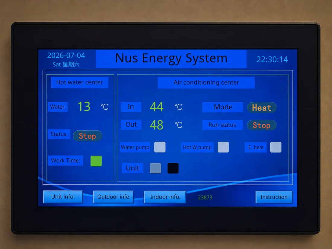
The EcoComfort demonstration system includes a practical control interface for monitoring hot water and air-conditioning operation. The interface supports system status review and operating mode settings for demonstration and technical discussion purposes.
Real demonstration control screen reference — not a final consumer UI design.
Project-Specific Design Assessment
EcoComfort is configured project by project. Suitability, capacity, tank sizing, terminal selection and controls depend on the building load, usage profile and installation conditions. Refrigerant-side work should be completed by qualified HVAC technicians, and performance depends on operating conditions — a project-specific assessment is always the starting point.
Important: Performance outcomes depend on building type, climate zone, system design, installation quality, electricity tariff structure and project-specific operating conditions.
Thermal Storage Operating Logic
The thermal storage tank lets the heat-pump unit charge ahead of demand. Once enough cooling or heating energy is stored, indoor terminals can keep running from the tank without the heat-pump unit operating at the same moment.
Distributed Expansion Architecture
For larger projects, a single subsystem can expand from one heat-pump unit up to 64 units. Unit 1 acts as the master controller, communicating with the expansion units over a 2-core, 0.75 mm² shielded cable; each unit connects independently to its own heat exchanger inside the storage tank.
Ask a technical question
Send your building type and current systems by email — we will respond with what an assessment would involve.